|
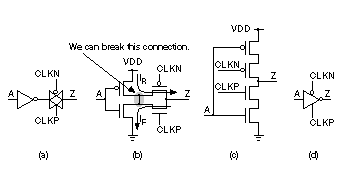
Chapter start Previous page Next page 2.5.3 Clocked InverterFigure 2.19 shows how we can derive the structure of a clocked inverter from the series combination of an inverter and a TG. The arrows in Figure 2.19(b) represent the flow of current when the inverter is charging ( I R ) or discharging ( I F ) a load capacitance through the TG. We can break the connection between the inverter cells and use the circuit of Figure 2.19(c) without substantially affecting the operation of the circuit. The symbol for the clocked inverter shown in Figure 2.19(d) is common, but by no means a standard. We can use the clocked inverter to replace the inverter–TG pairs in latches and flip-flops. For example, we can replace one or both of the inverters I1 and I3 (together with the TGs that follow them) in Figure 2.17(a) by clocked inverters. There is not much to choose between the different implementations in this case, except that layout may be easier for the clocked inverter versions (since there is one less connection to make). More interesting is the flip-flop design: We can only replace inverters I1, I3, and I7 (and the TGs that follow them) in Figure 2.18(a) by clocked inverters. We cannot replace inverter I6 because it is not directly connected to a TG. We can replace the TG attached to node M with a clocked inverter, and this will invert the sense of the output Q, which thus becomes QN. Now the clock-to-Q delay will be slower than clock-to-QN, since Q (which was QN) now comes one inverter later than QN. If we wish to build a flip-flop with a fast clock-to-QN delay it may be better to build it using clocked inverters and use inverters with TGs for a flip-flop with a fast clock-to-Q delay. In fact, since we do not always use both Q and QN outputs of a flip-flop, some libraries include Q only or QN only flip-flops that are slightly smaller than those with both polarity outputs. It is slightly easier to layout clocked inverters than an inverter plus a TG, so flip-flops in commercial libraries include a mixture of clocked-inverter and TG implementations. |
|||||
|
|
|||||
|
|||||


