Jun 23, 2016 -- In the injection molding industry, mold dimension accuracy is the most important factor to achieve high product quality and mass production ability. In addition to the help of the know-how of experienced engineers, the utilization of industrial global compensation method is a common practice used in the industry to achieve mold dimension accuracy.
Industrial global compensation is a method to apply the average shrinkage value of the injected part to compensate the product dimension. This is a good method to use when the shrinkage behavior of the injected part presents the consistent values throughout the whole part. However, the shrinkage values at different sections of the part are never uniform and some even exhibit a greater difference from one another. Thus, the industrial global compensation method is not the suitable approach to be applied in the real world of complex plastic product designs. Traditionally speaking, the trial-and-error method is a common practice used in the industry to produce plastic parts that meet the product requirements; however, the use of this method can be costly and also time-consuming. On top of this, the mold life can be drastically shortened due to the countless mold trials and modifications.
In order to avoid the problems mentioned above, CAE technology has been widely applied in the injection molding industry to help diagnose the causes of potential issues in the manufacturing process. Thus, common product defects such as warpage can be found at the early stage of product development to ensure product dimensional accuracy and assembly precision. To tackle the warpage issue head-on, Moldex3D has proposed a new “3D Volume Shrinkage Compensation Method (3D VSCM)” to improve the warpage problem. This method is to use different shrinkage values of different sections of the injected part to compensate the product dimension so that the targeted dimensional accuracy can be achieved throughout the whole injected part.
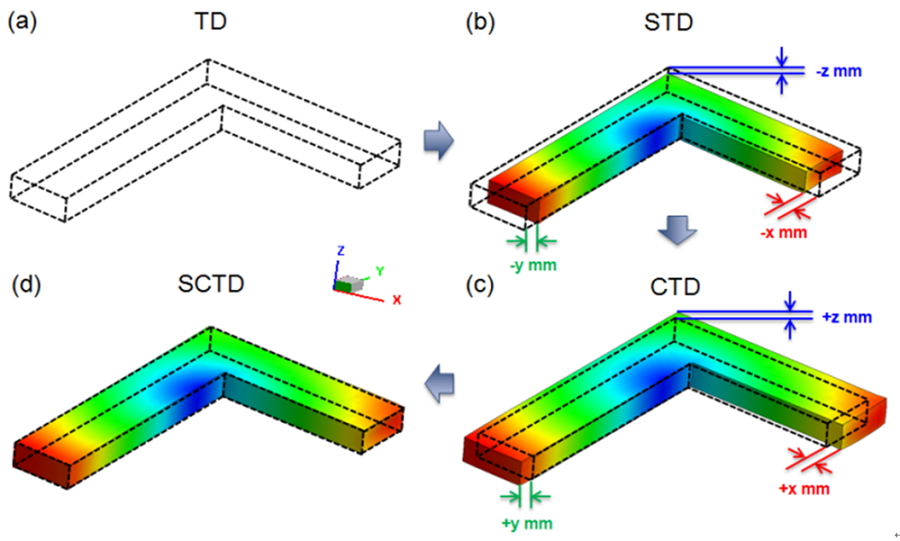
The following is a schematic flowchart of 3D VSCM. Fig.1 is an L-shape model. Fig.1 (a) is the desired geometry and dimension of Target Design (TD); (b) is the result of Moldex3D’s warpage Simulation on Target Design (STD). Next, since the shrinkage is three dimensional, to give better understanding, we define the shrinkage as –x, -y, and –z mm in three axes, respectively. Then, in order to compensate, the original design (TD) is revised with reverse of shrinkage. After revision, the modified design is shown as Compensate Target Design (CTD) (Fig. 1 (c)). Lastly, we performed a simulation on this CTD design. Fig. 1 (d) is the result of Simulation on Compensate Target Design (SCTD). We found that after this compensation, SCTD result is very close to TD.

Fig.1 A schematic flowchart of 3D VSCM
(a) TD: Target Design (with desired dimension)
(b) STD: Simulation result of the Target Design (TD)
(c) CTD: Compensate Target Design is the modified design with the reverse of STD shrinkage
(d) SCTD: Simulation result of the Compensate Target Design (SCTD)
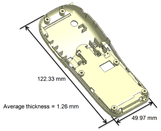
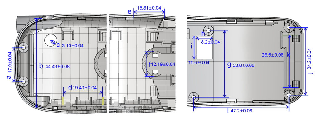
We will use a mobile phone case as an example for 3D VSCM demonstration. Its geometry and dimensional specification is shown in Fig. 2. There are twelve specification points with different tolerances on the mobile phone for the assembly purpose (Fig. 3).

Fig. 2 The geometry and dimensional specification of the mobile phone

Fig. 3 The mobile model is divided into 3 sections (top) and a to l
are the 12 specification points with different tolerances (bottom)
Fig. 4 is the 3D VSCM simulation results of the mobile phone. As shown below in STD-TI, the deviation of each specification point is not the same. That means the shrinkage direction of each specification point is different. We further apply the reversed shrinkage to compensate TD and the revised model, CTD2 is the modified design. The simulation result of CTD2 is SCTD2, which shows the 12 specification points all adhere to the desired dimension. The results have proved that 3D VSCM is the most ideal method to solve warpage issues; it not only helps reduce the number of mold trials and production costs, but also helps expedite the overall manufacturing process effectively.


