Apr 19, 2016 -- When producing thin-shell parts, internal stress can occur due to unoptimized molding process parameters such as cooling. Moreover, if the designer does not have comprehensive strength data to design the thin-shell part, it can cause structural or severe warpage problems. Also, if the factor of safety is too large, it might lead to material waste or more complex structures accompanied by higher molding costs.
2.5D Shell meshing technology is already widely used for performing structural analyses of injection-molded parts in a variety of industry sectors, including automotive. Traditionally, the importance of material properties is often underestimated in the structural analysis without taking into account the effects of fiber orientation, molding temperature and residual stress. However, this oversimplified analysis method usually leads to inaccurate structural simulation results.
To get more accurate and comprehensive structural analysis results, part designers have to integrate the simulation results into structural analysis via injection molding simulation software. However, mesh requirements vary between injection molding simulation and structural analysis. Structural analysis puts more emphasis on stress concentration area. Injection molding simulation, on the other hand, requires higher mesh resolution in the thickness direction, surface regions in particular. Therefore, various mesh element types and densities are required for performing injection molding simulation.
Moldex3D has developed 3D Mapping Shell technology to solve mapping problems between different analyses. Through its True 3D simulation technology, Moldex3D is able to transfer 3D injection molding simulation data to 2.5D Shell mesh elements and to deliver fast, efficient analysis results with high accuracy.
By using the Mesh Mapping function in Moldex3D FEA Interface, designers only need to export data and mesh information, and then import them into CAE structural analysis platform for further structural analyses.
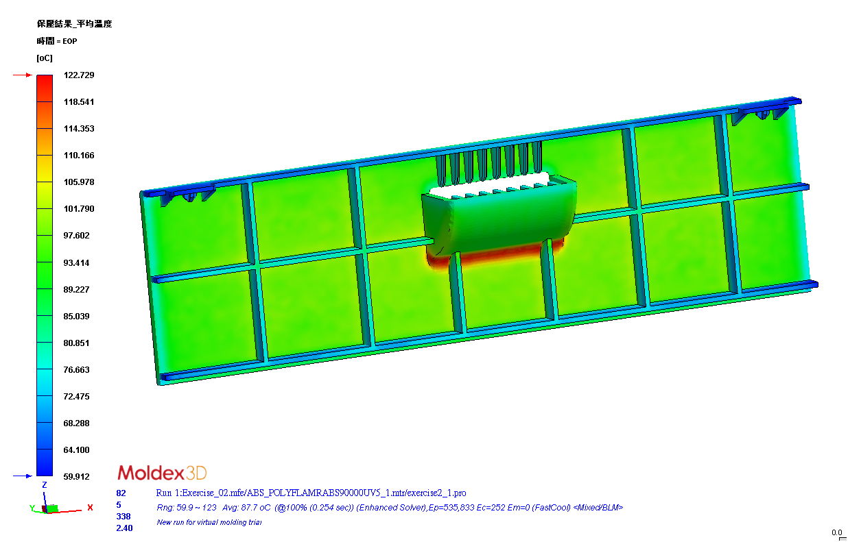
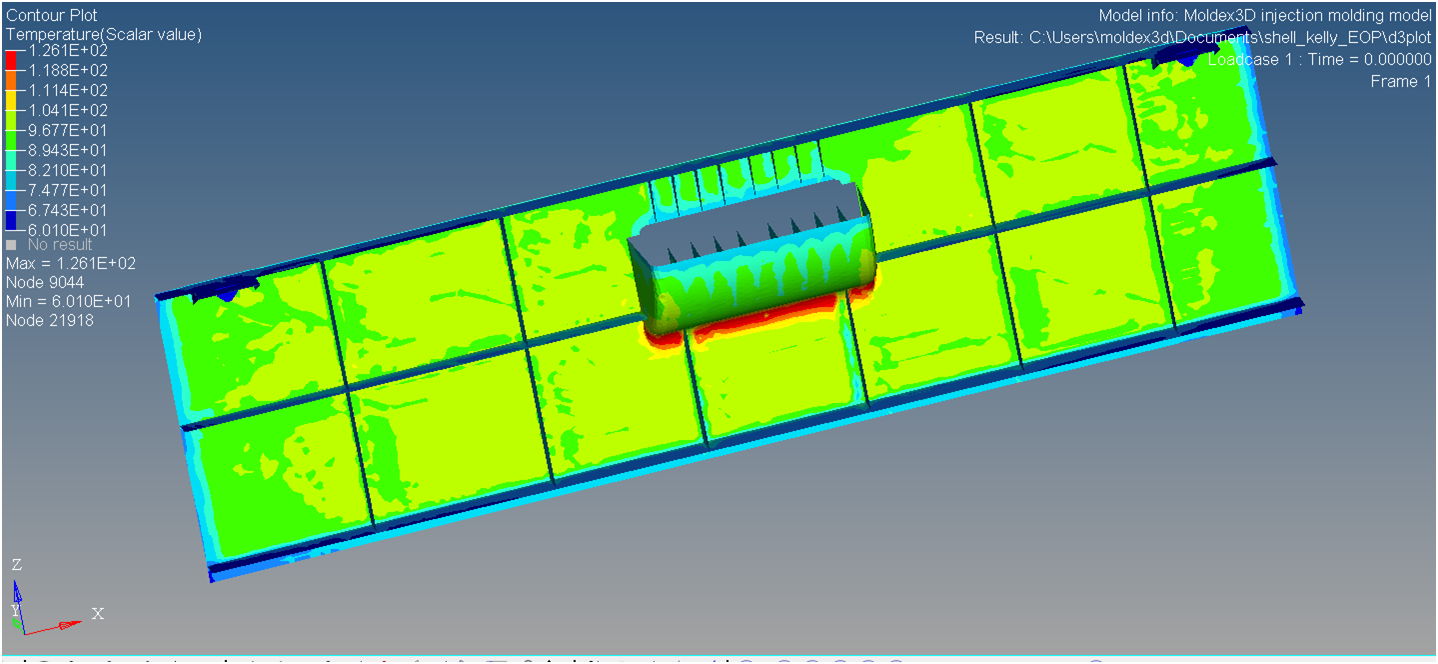
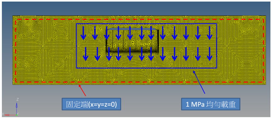
As shown in the following images, designers use 3D Mapping Shell technology to transfer results from 3D injection molding simulation to 2.5D structural model (Fig. 1). After specifying loading and boundary conditions (Fig. 2), designers can easily obtain analysis results on displacement and stress distribution (Fig. 3 and Fig. 4).
 |
 |
Fig.1 Temperature distribution analysis using 3D Moldex3D injection molding simulation (left).
Structural analysis of a 2.5D model coupled with results output from Moldex3D (right).
 Fig. 2 Set a uniform load to 1MPa with four ends fixed in the blue-circled area.
 Fig. 3 The displacement distribution analysis result.
 Fig. 4 The stress distribution analysis result.
3D simulation technology can generate more realistic analysis results than 2.5D technology; therefore, it has become a mainstream across industries. In order to help designers better assess the effects of molding processes and have better control over product quality, it’s necessary to fully integrate injection molding simulation with structural analysis.


