TOKYO — (BUSINESS WIRE) — August 27, 2015 — Toshiba Corporation (TOKYO:6502) today announced the launch of “TB9081FG”, a brushless motor [1] pre-driver IC enhanced to achieve functional safety[2], for use in electric power steering systems (EPS). Sample shipments will start on September 1st, 2015, with mass production scheduled to start in August, 2017.
This Smart News Release features multimedia. View the full release here: http://www.businesswire.com/news/home/20150827005402/en/

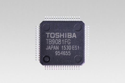
Toshiba: a brushless motor pre-driver IC "TB9081FG" for electric power steering systems(EPS) (Photo: Business Wire)
More and more safety-critical automotive systems, such as EPS, are required to meet the requirements of ASIL-D[3], the highest automotive safety integrity level prescribed in ISO 26262, “Road Vehicles – Functional Safety.”
The new IC integrates key main functions, including 3-phase pre-driver circuits [4], fail-safe relay pre-driver circuits [4] and motor current detection circuits [5], plus various failure detection circuits. An initial diagnosis circuit to detect latent faults in the failure detection circuits is also incorporated to secure higher functional safety.
Toshiba has also carried out a range of functional safety analyses to simulate various system failures and will provide customers with documentation, such as FMEDA[6], to support safety analysis and design.
Key Features
1. Failure detection circuits for functional safety
Built-in
VB over/under voltage detection circuit, VCC over/under voltage
detection circuit, over temperature detection circuits, and short
detection circuits [7].
2. Diagnosis circuit for failure detection
circuits for functional safety
A built-in diagnostic circuit
in the failure-detection circuit detects any latent faults.
3. Built-in fail-safe relay pre-driver circuits
Built-in
fail-safe relay pre-driver circuits drive the semiconductor relay
connected between the motor and MOSFET (driver) and between the
power-supply side and MOSFET (driver). The fail-safe relay pre-driver
circuit has a total of 5ch, three for the motor side and two for the
power-supply side. Both have dedicated input terminals, making
independent control possible.
4. Under voltage operation
Voltage
drop caused by cranking after idling reduction is accommodated by
improving battery operation voltage range down to 4.5V (min.).
5. Pre-Driver operation is selectable on failures
detection.
Customers can set the system to respond to
detected failures in one of two ways, using the input setting of the SPI
communication [8]. One setting uses this new IC to stop the
external MOSFET, the other switches to external control of the MOSFET
using the MCU (Micro Controller Unit). Selection can be made according
to the customer’s application or system, and for various systems.
|
Main Specifications |
||
| Part Number | TB9081FG | |
| Mass Production | August, 2017 | |
| Mass Production Volume | 1 million units per year | |
| Pre-driver channels |
11 channels (high side: 3 ch, low side: 3 ch, fail-safe side: 5ch) |
|
|
Operating
Voltage Range |
+ 4.5 to 18V | |
| Operating Temperature Range | -40 to 125°C | |
| Pre-driver input signal | Made for a direct control | |
| Detection Circuits | VB over/under voltage detection circuit, VCC over/under voltage detection circuit, over temperature detection circuits, and short detection circuits | |
| Motor Current Detection Circuits | Converts motor current to voltage and output to MCU | |
| Package |
LQFP64-P-1010-0.50E
(12.0mm × 12.0mm × 1.6mm) |
|


